

[Edit: LED technology has improved exponentially since this thread was started. Be aware that earlier posts may be somewhat outdated, and that you will likely find the most useful information in later updates. Y.R.]
In this thread, we'll talk about the do's and don'ts of LED headlight upgrades for your snowblower, and post videos and pictures of our successes.
There are many models of snowblowers that have a headlight circuit, In most cases, you can find a single wire that registers at anywhere from 12v to 20v AC (with no load) that is located somewhere on the engine, many times under the gas tank. Halogen lights are the typical light that comes with many of our snowblowers. Many of us want much more light than what the halogen bulb can give us, as well as better reliability than a halogen bulb. The search for something brighter and more reliable ends with the LED light. LED's (Light Emitting Diodes) are extremely efficient, very bright, and have thousands of hours of reliable use.
Since the lighting circuit is typically AC current at somewhere between 40-60hertz, if you just attach an LED light to the circuit you'll get pulsing light (think on and off 40-60 times a second) This is caused by the nature of an LED, because an LED is polarity sensitive, and has no warm-up or cool down time when compared to a halogen bulb filament, the LED will flicker noticeably. The flickering of an LED on AC current is mildly annoying to many people, but VERY annoying when you are attaching it to a moving object like a snowblower. An LED that is in motion when attached to AC current (for reasons I won't even begin to get into) flickers much more noticeably. To test this for yourself, take a strand of LED Christmas lights, plug them in, and then swing them in front of you at arm's length, you'll see a strobing or flickering effect.
You can see many LED headlight upgrade videos on youtube like this one, where you can definitely see the flickering or strobing of the LED's. You can see the effect the flicker has on the video camera, you get weird tracks that go from top to bottom of the video frame.
1. EXAMPLE OF IMPROPER LED LIGHT INSTALL- NOTICE THE FLICKERING
2. EXAMPLE OF YET AGAIN AN IMPROPER LED LIGHT INSTALL- NOTICE THE FLICKERING
This is what it looks like once you add a bridge rectifier, even though you’ll see a tiny bit of flicker in the video, in person there is none, you also can notice that there is no “tracking” effect like in the other videos.
The problem of light flicker is solved by using a full wave bridge rectifier.
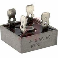
A bridge rectifier takes AC current and changes it into DC current using 4 diodes.
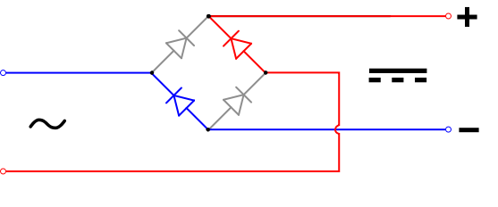
By connecting the positive and negative from your LED light(s) to the DC output of your bridge rectifier, and then connecting your single headlight circuit wire to one of the AC inputs of the bridge rectifier (it doesn't matter which AC input) and then attaching a wire from the metal of your snowblower to the other AC input you will have light! For safety purposes, it is recommended that you place a fuse on the headlight circuit wire before the bridge rectifier which should be about 5 amps rated fast blow, and then a fuse on the positive wiring between your bridge rectifier and your LED light that should be about ~1amp fast blow fuses. These fuse ratings are assuming you are using a headlight circuit that is rated for ~1amp at about 18volts, some headlight circuits are rated for 2, 3, or more amps, so using an amperage calculator like this one can help with both your LED light selection and your fuse selection. Volts/Amps/Watts Converter
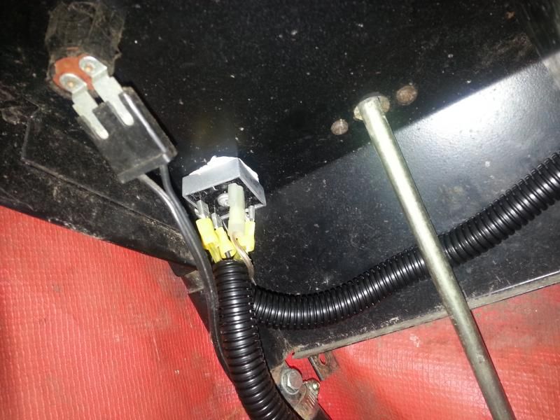
Here's a pic of how I installed my bridge rectifier, I mounted it right next to my keyed switch that is on my handlebar console. I also used heat sink paste to couple the bridge rectifier’s metal casing to the console’s metal. I know this is way overkill, but my bridge rectifier came with the paste, and it was an easy application of some paste. The bridge rectifier I used is rated at 50amps 100volts KBPC5010 Bridge Rectifier | Alltronics
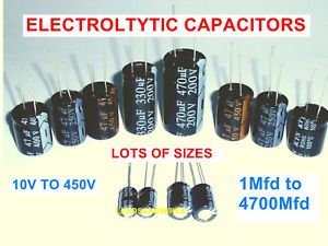
UPDATE: Using two 2200mfd 50v capacitors may be needed to clean up the voltage ripple that comes off of the DC output on your bridge rectifier. Some LED lights are sensitive to this ripple and may fail prematurely. Simply adding these capacitors in parallel on the DC output side of the bridge rectifier is a good precaution. Wire in the Capacitor(s) between the LED light(s) and the bridge rectifier. So the positive and negative of the bridge rectifier will go to the positive and negative of the capacitor. Then the positive and negative of the capacitor then get wired to the LED(s) positive and negative.
When choosing your LED lighting you typically have spotlights or flood lights available. Spotlights have a more pinpoint dispersion with very little side spill of light. Flood lights illuminate a wider area, and with the short distances (from LED light to relevant distance in front of your snowblower) you’ll want as wide dispersion as possible, or else you’ll get a tiny area in front of you illuminated. I made sure to get floodlights that were rated for voltage below what my snowblower headlight circuit tests at and above, so being that my snowblower headlight circuit tests at 18volts I picked a set of LED floodlights that were rated for 9-32 volts. I wanted to make sure that I would never be putting the floodlights in danger with whatever voltage the headlight circuit was producing, even a small voltage peak is accounted for. The floodlights I chose are 9 watts each, which is as much as my headlight circuit is rated for.
For those that appreciate a short(ish) video with some basic points noted here is a video.
https://www.youtube.com/watch?v=ZZwebMaiyBY
In this thread, we'll talk about the do's and don'ts of LED headlight upgrades for your snowblower, and post videos and pictures of our successes.
There are many models of snowblowers that have a headlight circuit, In most cases, you can find a single wire that registers at anywhere from 12v to 20v AC (with no load) that is located somewhere on the engine, many times under the gas tank. Halogen lights are the typical light that comes with many of our snowblowers. Many of us want much more light than what the halogen bulb can give us, as well as better reliability than a halogen bulb. The search for something brighter and more reliable ends with the LED light. LED's (Light Emitting Diodes) are extremely efficient, very bright, and have thousands of hours of reliable use.
Since the lighting circuit is typically AC current at somewhere between 40-60hertz, if you just attach an LED light to the circuit you'll get pulsing light (think on and off 40-60 times a second) This is caused by the nature of an LED, because an LED is polarity sensitive, and has no warm-up or cool down time when compared to a halogen bulb filament, the LED will flicker noticeably. The flickering of an LED on AC current is mildly annoying to many people, but VERY annoying when you are attaching it to a moving object like a snowblower. An LED that is in motion when attached to AC current (for reasons I won't even begin to get into) flickers much more noticeably. To test this for yourself, take a strand of LED Christmas lights, plug them in, and then swing them in front of you at arm's length, you'll see a strobing or flickering effect.
You can see many LED headlight upgrade videos on youtube like this one, where you can definitely see the flickering or strobing of the LED's. You can see the effect the flicker has on the video camera, you get weird tracks that go from top to bottom of the video frame.
1. EXAMPLE OF IMPROPER LED LIGHT INSTALL- NOTICE THE FLICKERING

A bridge rectifier takes AC current and changes it into DC current using 4 diodes.

By connecting the positive and negative from your LED light(s) to the DC output of your bridge rectifier, and then connecting your single headlight circuit wire to one of the AC inputs of the bridge rectifier (it doesn't matter which AC input) and then attaching a wire from the metal of your snowblower to the other AC input you will have light! For safety purposes, it is recommended that you place a fuse on the headlight circuit wire before the bridge rectifier which should be about 5 amps rated fast blow, and then a fuse on the positive wiring between your bridge rectifier and your LED light that should be about ~1amp fast blow fuses. These fuse ratings are assuming you are using a headlight circuit that is rated for ~1amp at about 18volts, some headlight circuits are rated for 2, 3, or more amps, so using an amperage calculator like this one can help with both your LED light selection and your fuse selection. Volts/Amps/Watts Converter
Here's a pic of how I installed my bridge rectifier, I mounted it right next to my keyed switch that is on my handlebar console. I also used heat sink paste to couple the bridge rectifier’s metal casing to the console’s metal. I know this is way overkill, but my bridge rectifier came with the paste, and it was an easy application of some paste. The bridge rectifier I used is rated at 50amps 100volts KBPC5010 Bridge Rectifier | Alltronics

UPDATE: Using two 2200mfd 50v capacitors may be needed to clean up the voltage ripple that comes off of the DC output on your bridge rectifier. Some LED lights are sensitive to this ripple and may fail prematurely. Simply adding these capacitors in parallel on the DC output side of the bridge rectifier is a good precaution. Wire in the Capacitor(s) between the LED light(s) and the bridge rectifier. So the positive and negative of the bridge rectifier will go to the positive and negative of the capacitor. Then the positive and negative of the capacitor then get wired to the LED(s) positive and negative.

When choosing your LED lighting you typically have spotlights or flood lights available. Spotlights have a more pinpoint dispersion with very little side spill of light. Flood lights illuminate a wider area, and with the short distances (from LED light to relevant distance in front of your snowblower) you’ll want as wide dispersion as possible, or else you’ll get a tiny area in front of you illuminated. I made sure to get floodlights that were rated for voltage below what my snowblower headlight circuit tests at and above, so being that my snowblower headlight circuit tests at 18volts I picked a set of LED floodlights that were rated for 9-32 volts. I wanted to make sure that I would never be putting the floodlights in danger with whatever voltage the headlight circuit was producing, even a small voltage peak is accounted for. The floodlights I chose are 9 watts each, which is as much as my headlight circuit is rated for.
For those that appreciate a short(ish) video with some basic points noted here is a video.
https://www.youtube.com/watch?v=ZZwebMaiyBY
")


